Text-to-CAD AI Tools: 2026 Guide + Free Options
How text-to-CAD AI actually works, which tools output editable STEP files versus pretty meshes, how to write prompts that work, and a step-by-step first model.


You can type "a 60mm mounting bracket, 8mm thick, with four M5 clearance holes on a 40mm square pattern" and get back a watertight, editable solid you can open in Fusion 360 and hand to a machine shop. That is genuinely possible in 2026. Here is what trips up almost everyone before they even start: most of the tools marketed as text-to-CAD AI tools do not do that at all. They hand you a mesh. A mesh is a sculpture, not a CAD model.
That distinction is the whole game, and it is the reason this guide exists. Most coverage of this space is either a 2023-era research paper or a single vendor's landing page, and both skip the one question an engineer actually cares about: can I edit the thing afterward? I'm going to walk you through how the technology works, which tools produce engineering-grade output, how to write a prompt that returns something usable, and a step-by-step first model you can reproduce for free. No hype.
What Is Text-to-CAD AI?
Text-to-CAD AI is the practice of generating editable, parametric CAD geometry from a natural-language prompt, so that a description like "a 600mm manhole cover, 50mm thick, with a 200mm center hole" produces a solid model with real dimensions you can modify afterward. The key word is parametric: the output carries feature history (sketches, extrudes, fillets) rather than a frozen surface.
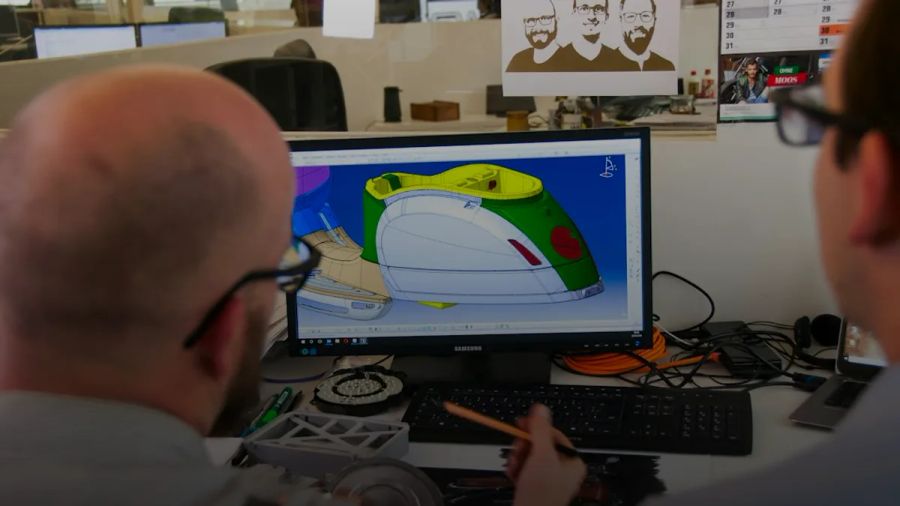
Under the hood, the serious tools do not predict triangles. They predict a construction sequence. Mohammad Sadil Khan and his co-authors built Text2CAD, a NeurIPS 2024 Spotlight, which trains a transformer to emit a sequence of sketch-and-extrude operations from prompts graded from "beginner" to "expert" complexity. That sequence is effectively the same list of steps a human designer would perform in SolidWorks, which is why the result is editable instead of baked.
Production tools go a step further by pairing a large language model with a geometry engine that can inspect its own output. Zoo's Zookeeper agent, built by the CAD company Jess Frazelle co-founded, generates code in its own CAD scripting language (KCL) and uses engine-level tools to snapshot and debug geometry mid-generation. The model writes CAD operations. The kernel checks whether they actually produce a valid solid. That feedback loop is closer to how AI agents operate than to how an image generator works, and it is why the newest tools are far more reliable than the 2024 research demos.
Text-to-CAD vs. Text-to-3D: Why the Difference Matters
Here is the thing nobody selling these tools wants to say plainly: text-to-3D and text-to-CAD are different product categories that happen to share a prompt box.
Text-to-3D generators like OpenAI's Shap-E (12,261 GitHub stars) and Point-E (6,896 stars) produce implicit functions, meshes, or point clouds. They are brilliant for game assets, VFX, concept art, and some 3D printing. Ask Shap-E for "a chair that looks like an avocado" and you get a lovely organic mesh. Ask it for a gasket with a 2mm wall and a sealed bolt circle, and you get a blob that looks approximately right and is dimensionally meaningless.
Text-to-CAD, by contrast, targets manufacturing. The output is a boundary representation (B-rep) solid with real edges, faces, and a feature tree. You can measure it, constrain it, and export it as a STEP file that SolidWorks or Onshape treats as native geometry.
| Dimension | Text-to-3D (mesh) | Text-to-CAD (parametric) |
|---|---|---|
| Output | Mesh, point cloud, NeRF | B-rep solid + feature history |
| Native formats | STL, OBJ, GLTF | STEP (ISO 10303), native parametric tree |
| Editable afterward? | Only as dumb geometry | Yes: sketches, extrudes, dimensions |
| Dimensional accuracy | Approximate | Exact to stated values |
| Best for | Games, VFX, art, some 3D printing | Mechanical parts, assemblies, manufacturing |
| Example tools | Shap-E, Point-E, Meshy | Zoo Zookeeper, Text2CAD, LLM + OpenSCAD |
If you remember one thing from this guide, make it this table. A mesh cannot become a parametric model by wishing. Converting STL back into editable features is a reverse-engineering job, and it is painful enough that I wrote a separate piece on reverse-engineering with agents. Pick the right category before you pick a tool.
Top Text-to-CAD AI Tools in 2026 (and What They Cost)
The landscape has consolidated since the research-paper era. These are the options worth your time, ranked by how usable they are for real engineering work.
- Zoo Design Studio (Zookeeper) — The most mature AI-native CAD platform. Zookeeper is a conversational agent built into Zoo Design Studio (Mac, Windows, Linux) that generates production-ready, fully editable models and exports valid STEP. It has a free browser tier to experiment with, paid plans for heavier use, and Zoo exposes developer APIs for programmatic generation according to its docs. This is where I'd send a skeptical mechanical engineer first.
- Text2CAD (open research model) — The NeurIPS 2024 model (488 stars, 80 forks as of October 2026) that produces editable sketch-and-extrude sequences. It is a research codebase, not a product, but it is the clearest proof that language-to-parametric-sequence works and it is free to run.
- Shapr3D — A hybrid. Originally built for iPad and Apple Pencil, now on macOS and Windows, it is a traditional direct-modeling CAD app that is bolting on AI-assisted features rather than being AI-native. Good if you want a real modeler with AI help, not a prompt box.
- Autodesk Fusion generative design — Not text-to-CAD, but frequently confused with it. You give it loads, materials, and manufacturing constraints, and it explores thousands of structurally optimized geometry variants. It is form-finding from engineering goals, not from free text.
- LLM + OpenSCAD / FreeCAD (DIY) — The free, flexible path. Any frontier chat model can write OpenSCAD or FreeCAD Python token by token. More on this below, because it is the budget option that actually works.
On pricing: the honest summary is that you can start for $0. Zoo's browser tier and the open-source research tools cost nothing to try, and the DIY LLM path only costs whatever you already pay for an AI subscription. Dedicated commercial CAD apps like Shapr3D and Fusion carry the usual per-seat subscription fees, which is why hobbyists gravitate to the free tiers and the scripting route.
File Formats and CAD Compatibility: STEP, STL, and Parametric Trees
This is where "AI CAD model" claims live or die. The format determines whether an engineer can do anything with the file.
STEP (ISO 10303) is the neutral exchange standard every serious CAD package reads. A text-to-CAD tool that exports valid .step or .stp with intact topology gives you geometry SolidWorks, Fusion 360, and Onshape treat as real solids. You can measure it, add features to it, and mate it in an assembly.
STL, OBJ, and GLTF are mesh formats. They describe a surface as triangles. You can 3D print an STL, but you cannot natively edit it as parametric features. Fusion will import it as a mesh body, and converting that to a solid is lossy and manual.
Native parametric trees are the richest output: the full feature history in the tool's own format. Zoo's models carry this, which is what makes "change the hole diameter to 12mm" a one-line edit instead of a remodel.
So, can you edit AI-generated CAD in SolidWorks or Fusion 360? Yes, if the tool exported STEP or a native feature tree. If it exported STL, you can open it, but you are editing a mesh, not a model. Always check the export options before you commit to a tool. If STEP is not on the list, you are looking at a text-to-3D product wearing a CAD label.
How to Write Effective Prompts for Text-to-CAD
The single biggest predictor of a usable result is whether your prompt contains numbers. Zoo's own before-and-after examples make this obvious: "a manhole cover" returns a vague disc, while "a manhole cover with cuts for lifting, 600mm diameter, 50mm thick, with a 200mm hole in the middle" returns something you could actually quote.
Treat the prompt like a drawing callout, not a wish. Here is what consistently works:
- State every dimension in explicit units. Say "80mm", not "about 8cm" and never "medium-sized." Pick millimeters and stay there.
- Name the base feature first, then the modifications. "A rectangular plate, 100mm x 60mm x 5mm, then add..." gives the model a clean starting solid.
- Specify hole patterns precisely. Count, diameter, spacing, and reference edge: "four 5mm holes, 10mm from each corner."
- Describe manufacturing intent when it matters. "with 2mm fillets on vertical edges" or "3mm uniform wall thickness" nudges the model toward something makeable.
- Iterate in small steps. Generate the base, verify it, then prompt "now add a 20mm boss on the top face." One change at a time beats one giant paragraph.
- Reference standards by name where they exist: "M5 clearance holes," "standard DIN rail cutout." The models have seen those terms.
Vague prompts do not fail quietly. They return a confident, wrong solid, and you will not notice the 79.4mm-where-you-wanted-80mm drift until you measure it. Write like an engineer, get engineering back.
Step-by-Step Tutorial: Generating Your First AI CAD Model
Let's make something real: a simple mounting bracket, exported as STEP. This uses Zoo's free browser tier, but the flow generalizes to any parametric tool.
- Open the free tool. Go to Zoo Design Studio's browser demo or launch the desktop app (Mac, Windows, or Linux). No install is needed for the browser version.
- Write a dimensioned prompt. Enter: "An L-shaped mounting bracket, base 80mm x 50mm x 6mm thick, with a vertical wall 50mm tall and 6mm thick along the 50mm edge. Four 5mm holes in the base on a 60mm x 30mm rectangular pattern. 3mm fillets on the inside corner."
- Generate and read the result critically. The agent returns a solid. Do not admire it. Rotate it and check the wall is on the correct edge and the holes landed where you specified.
- Verify dimensions with the measure tool. Measure the base, the wall height, and one hole diameter against your prompt. This is the step 90% of tutorials skip, and it is the only one that matters.
- Iterate with a follow-up prompt. If the holes are 5mm but you wanted 5.5mm clearance, prompt: "change all four base holes to 5.5mm diameter." Confirm only that changed.
- Export to STEP. Choose
.step(or.stp) from the export menu. If you only see STL/OBJ, you are in a mesh tool. Stop and switch. - Open it downstream. Import the STEP into Fusion 360 or Onshape. It should arrive as a solid body you can add features to, not a mesh. Add a chamfer to prove it is editable.
If you want to see the end-to-end prompt-to-STEP flow on video before trying it, this walkthrough covers it in a few minutes:
That is the whole loop: prompt, verify, iterate, export, confirm editability. Run it twice and you will have better instincts for prompting than most of the marketing copy will give you.
Accuracy, Limitations, and When Not to Trust AI-Generated CAD
Now the part the product pages skip. How accurate are AI-generated CAD models for manufacturing? Honestly, the answer in 2026 is: good enough for brackets, enclosures, and simple fixtures, and not yet good enough to trust blind for anything with tight tolerances or safety implications.
The failure modes that show up repeatedly in these tools are worth internalizing before you ship anything:
- Dimension drift. You ask for 80mm and get 79.4mm. The model understands shape better than it respects exact magnitude, so always measure the output against the prompt.
- No GD&T. Geometric dimensioning and tolerancing, the language of whether a part actually fits, is essentially absent. The tools give you nominal geometry, not tolerances.
- Design-for-manufacturing blind spots. The model will happily generate a feature that cannot be milled, molded, or printed without support. It optimizes for "matches the description," not "is cheap to make."
- Assemblies drift apart. Multi-part prompts frequently return parts that do not mate cleanly. Single parts are far more reliable than assemblies today.
So treat AI-generated CAD as a fast first draft, not a finished deliverable. The engineer's job shifts from drawing the geometry to specifying, verifying, and correcting it. Which answers the anxious question directly: no, this does not replace CAD designers. It replaces the first 20 minutes of their drawing time and leaves the judgment, the tolerancing, and the manufacturing review exactly where they were. This is the same pattern I keep seeing across tools. The AI collapses the easy middle and raises the value of the human review at the edges, which is the whole thesis behind generative AI vs agentic AI.
The DIY Path: An LLM Plus OpenSCAD or FreeCAD
The free, flexible alternative to any commercial product is to let a language model write CAD code for you. OpenSCAD defines solids through its own description language using constructive solid geometry, and FreeCAD is fully Python-scriptable under an LGPL license. Both are compilation targets an LLM can hit, because both represent a model as text the model can generate token by token. Simon Willison has written extensively about how reliably current frontier models generate working code in niche languages, and OpenSCAD is exactly that kind of target: small, declarative, and well represented in training data.
The workflow is simple: describe the part to a frontier model, ask it for OpenSCAD source, paste the code into OpenSCAD, and render. When the dimensions are wrong, you edit numbers in the code directly, which is often faster than re-prompting. This is the same move as vibe coding, applied to geometry instead of web apps, and the models that are good at code are good at this.
One honest caveat from my own testing. Based on the local-model coding results I maintain at kunalganglani.com/llm-benchmarks, the gap between a frontier model and a quantized local model on structured code generation is real, and OpenSCAD punishes it hard. A small syntax or CSG-logic slip produces a blank render, not a partial one. The quantization quality cliffs I documented there are model-family-specific, so a heavily quantized 7B running on your laptop will fumble nested transforms that a frontier model writes cleanly. In my own local LLM runs for those benchmarks, unified memory on Apple Silicon lets a bigger model load, but throughput is the real trade. That matters when you want the DIY loop to iterate in seconds rather than minutes. For CAD scripting specifically, reach for a strong model. Tools like Claude Code handle the iterate-render-fix loop well because they can hold the whole script in context. If you want to run it locally anyway, expect to validate every render before you trust a number.
The upside of the DIY path is total control and zero cost. The downside is that OpenSCAD's CSG output is a mesh, not a B-rep, so if you need a true STEP file you will want the FreeCAD Python route, which can produce proper parametric solids. For hobby parts and 3D prints, OpenSCAD is more than enough, and it pairs beautifully with the kind of scripted, reproducible workflow I lean on across my dev tools and AI workflow setup.
Where does this go next? The research trajectory is clear: the tools that win will be the ones that close the loop like agents. Generate geometry, check it against the kernel and against stated constraints, and self-correct before a human ever sees it. Zookeeper's engine-level debugging is the early version of that. Within a couple of years, "text-to-CAD" will stop meaning "prompt returns a shape" and start meaning "describe the requirements and the agent iterates to a manufacturable, toleranced part." When that lands, the bottleneck moves entirely to specification. The engineers who thrive will be the ones who can state exactly what they want. Start practicing that now, one dimensioned prompt at a time.
Photo by ThisisEngineering on Unsplash.
Continue reading

Claude Artifacts for UI Design: I Gave It an Impossible Dashboard Challenge [2026]
I asked Claude Artifacts to build a full drone fleet management dashboard from a vague brief. Here's what happened across 14 iterative prompts — and where AI-generated UI actually breaks down.
DaVinci Resolve 21 AI Features: I Tested Them on a Real Project [2026 Review]
I put DaVinci Resolve 21's new AI features through a real editing project. IntelliTrack, uTalk, Voice to Subtitle, and Color Slice — here's what actually works and what's still rough.

Jev vs Laya Head-to-Head [2026]: Typed-Output AI
A transparent first-look comparison of Jev and Laya, two task-specific AI models pitched against GPT and Llama. Here's what's verifiable, what isn't, and when a typed-output model beats a full LLM.
Design to Code Tools Benchmark [2026]: 5 Tools, Real Diffs
I ran the same messy SaaS dashboard through 5 design-to-code tools and scored the outputs on a11y, semantics, bundle size, editability, and fidelity. Here’s the reproducible harness—and what actually wins in production.

Kunal Ganglani (2026, October 17). Text-to-CAD AI Tools: 2026 Guide + Free Options. Kunal Ganglani. Retrieved October 17, 2026, from https://www.kunalganglani.com/blog/text-to-cad-ai-tools
Frequently Asked Questions
Will text-to-CAD AI replace CAD designers and engineers?
No. In 2026 these tools produce fast first drafts of simple parts but miss tolerances, design-for-manufacturing checks, and reliable assemblies. The designer's role shifts from drawing geometry to specifying, verifying, and correcting it, which is where the real engineering judgment lives.
What is the practical difference between Fusion 360 generative design and text-to-CAD?
Generative design in Fusion 360 takes engineering constraints like loads, materials, and manufacturing method, then explores thousands of structurally optimized shapes. Text-to-CAD takes a free-text description and produces one model matching it. One optimizes from goals; the other translates language into geometry.
Do text-to-CAD AI tools work offline?
The commercial agents like Zoo's Zookeeper run in the cloud or a desktop app that calls hosted models, so they need a connection. The DIY path using a local LLM plus OpenSCAD or FreeCAD can run fully offline, though a heavily quantized local model will make more code errors than a frontier one.